by Art Gardner et. al.
Ever try to adjust your ‘49’s brakes and just couldn’t get them right? If so, you are not alone. Many of us have adjusted our brakes at one time or another by doing just the following. You stick your brake adjusting tool in the slot at the bottom of each backing plate, push down on the “star wheel” inside to tighten the brakes, while listening as it clicks against the lower brake shoe spring, and raise the star wheel to loosen the brakes. And that’s all there is to it, right? Not totally, since in our experience success sometimes eludes you. Leaving aside the contention by some that ’49 drum brakes are very mysterious things indeed, the main thing is that adjusting them involves more than the simple procedure outlined above. There are additional procedures you can do to get a ’49 to stop like it should, which is the topic at hand.
Turn to page 63 in your ’49 shop manual, on which is set forth the official procedures for adjusting brakes. The first step is to get under the car and adjust the “Brake Pedal Operating Rod” between the bottom of the brake pedal and the master cylinder in order to have 1/8 inch (0.3175 cm.) clearance between the rod and the master cylinder piston. This is not particularly difficult and, as the manual says, “This adjustment is important…”, since if not done right the brakes will drag or have excessive play.
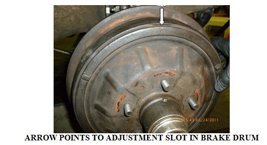
For the second step you’ll need a .015 inch (0.04 cm.) flat feeler gauge. Remove the wheels and refer to the photo of a brake drum below. You’ll see that there is a narrow “adjusting” slot in the perimeter of the outer face of the drum. (Didn’t know it was there? You are not alone on this either!)
ARROW POINTS TO ADJUSTMENT SLOT IN BRAKE DRUM
Turn the brake drum until the slot is opposite the “lower end of secondary or rear [brake] shoe”. This would be about the “8 o’clock” position on the passenger’s side of the car or the “4 o’clock” position on the driver’s side of the car Insert the feeler gauge and, following the procedure in the manual, raise or lower the star wheel with your brake tool to “establish a clearance of .015 inch at 1½ inches [3.8 cm.] from each end of secondary shoe”. This would be about the “8 o’clock” and “10 o’clock” positions on the right side of the car or “2 o’clock” and “4 o’clock” positions on the left side of the car.
Couldn’t get the required clearances at either or both positions? If so, the third step is to get the secondary brake shoe centered vertically on the backing plate so that there is .015 inch clearance at both positions. To do this, refer to Figure 56 on page 65 of your shop manual. You’ll see at the top of the brake mechanism on each wheel is the “anchor pin”, onto which the two “brake shoe return springs” are hooked. You can’t see it, but this anchor pin is an “eccentric”, which means it can be adjusted up and down and right to left.
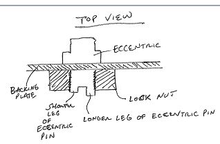
To adjust the anchor pin first refer to the illustration below, and then stick your head under the car to the rear of the backing plate. You’ll see that the back of the anchor pin is in the form of a bolt, onto which is screwed a large 15/16 inch (2.4 cm.) diameter lock nut. Also, the back end of the anchor pin has a large slot for inserting a flat tool such as a large screwdriver or the end of your brake adjusting tool. You’ll notice that one leg of the slot is longer than the other.
To adjust the anchor pin, the shop manual merely says to “loosen the anchor pin lock nut….and turn eccentric anchor pin in direction required to equalize clearances. Re-tighten lock nut and check clearances.” This statement doesn’t provide much detail since it doesn’t tell you which direction to turn the back of the anchor pin for the brake shoe clearances needed and, in addition, doesn’t tell you the best way to do so.
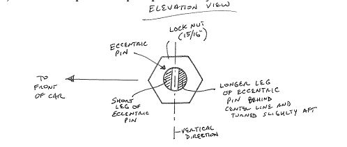
The answer to this is in a separate manual called “Manufacturing Information”. This publication, dated October 1948, was circulated in the Cadillac factory in Detroit to foremen and others to provide instructions on assembling ’49 Cadillacs. At the bottom of page 5-A-1 it says: “Assemble the anchor pin so the long end at the slotted [inner or back] end is just back to rear of vertical center line.” (Authors’ note: we interpret this somewhat unclear sentence to mean the longer leg of the slotted pin should be in a vertical position toward the back of the car with its upper tip pointing slightly toward the rear of the car, as in the drawing below.) This locates the pin for subsequent up and down adjustment.
And how to do so? We found the easiest way to turn the anchor pin is to loosen the lock nut, insert the blade of your brake adjusting tool in the slot, get a good grip on it and, to get a .015 inch clearance at both the upper and lower positions, turn it toward the rear of the car if you need to lower the secondary brake shoe and toward the front of the car to raise it. When finished, it says in Manufacturing Information to torque the lock nut to 70 foot-pounds. This procedure should yield the best possible brake pedal for your car, while minimizing drag on the brakes.