Category Archives: Heater

Heater Removal and Rebuilding

Thanks to Fab for posting this on the CLC forum

just rebuilt my entire heater system about 3 or 4 months ago. To remove it, you need to do the following:

1. Unhook the electrical connections under the dash. I think there are only two wires, a fused power source, and a wire to your underseat heaters.

2. Detach the two control levers.

3. Unscrew the metal bracket holding the thin copper capillary tube in place.**

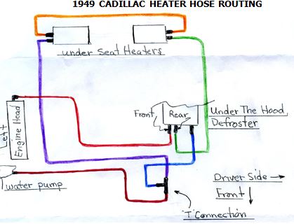
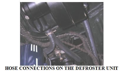
4. In the engine compartment, remove the heater hoses from the bottom of the unit.

5. Remove all the bolts attaching the unit to your firewall. There’s a rubber gasket between the heater unit and the firewall. Mine had somehow sealed the unit to the firewall, so I had to pry it off. (You can buy a replacement here: http://www.steelerubber.com/heater-gasket-70-0448-31)

6. Once you get everything removed and the unit free, start to pull it out gently. You’ll see a vent cable attached to the side of it. Unscrew and release this.

**MOST IMPORTANT THING: make sure not to pinch or break the thin copper capillary tube. If you damage this, your heater valve will be useless. Best to have somebody on the inside helping guide the unit out.

Once you get the unit out, you can remove the two heater valves. I sent mine to Jim Tucker: http://www.heatercontrolvalve.com/. I think it was about $250 to rebuild both valves.

MORE ON HOOKING UP HEATER HOSES

Chapter member Daniel Parker of Palmdale, California sent in the diagram below and wrote that he thought it “might help the next time someone asks how to route heater hoses”. To aid in using Daniel’s diagram, members may want to refer to the June ’09 issue of the Times, in which there appeared an article describing in text the routing of these hoses.

dec 10 heater


dec 10 heater 2

newsletter

HOW TO HOOK UP YOUR 49s UNDER HOOD HEATER HOSES

Before hooking up the hoses, observe that the defroster core and motor on the driver’s side firewall has three pipes pointing downwards. Two of these pipes are on the inboard side of the defroster, one of which is in front of the other. The third pipe is at the outboard side of the defroster.

Directly under the defroster, sitting on the frame rail, is a T shaped pipe fitting (to which hoses will be connected). The T connection sits on the frame in an upside down position, something like this ?, with the axis of its bottom facing longitudinally toward the front and back of the car.

From the pipe connection at the back of the driver’s side cylinder head, a short hose goes through an L-shaped elbow pipe (which looks like this: ?) to the front pipe of the two inboard pipes on the defroster. From the back pipe of the two inboard pipes on the defroster, another hose runs under the car’s body to the driver’s side under-seat heater. A third hose runs from the outboard pipe on the defroster straight down to the upward facing pipe on the ? (or T) connection. (See the photo on the next page.)

From the second pipe on the driver’s side under-seat heater, a hose runs across the top of the frame to the passenger’s side under-seat heater. From the second pipe on the passenger’s side under-seat heater, a hose runs back over the frame to the driver’s side of the car’s underside, and then all the way to the backward facing pipe on the ? (or T) connection. Another hose runs from the front facing pipe on the ? (or T) connection, up through a clip on the inner fender, to the pipe on the left side of the water pump.

june 09 heater

newsletter