Category Archives: Hydro-Lectrics

THE INFAMOUS HYDROLECTRIC SYSTEM PART II

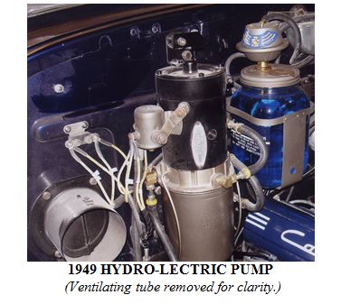
In Part 1 in the December 2011 issue, I outlined the basic operating principles of Hydro-lectric systems, which were used by several automobile manufacturers during the1940s. Essentially, the Hydro-lectric system was an early version of power windows, seat and top which utilized a pump and reservoir containing (originally) brake fluid, a closed loop of metal lines and flexible hoses, hydraulic pistons, switches, springs, and solenoids to operate the various components.
In this second, and final, installment, I’d like to outline various trouble-shooting and testing procedures, and touch upon more technical aspects of the system. First, check the battery. For efficient operation, battery gravity reading should not be less than 1200 or equivalent voltage. In laymen’s terms, be sure the battery is fresh and fully charged. In some cases, a slightly discharged battery may be sufficient to run the hydraulic motor, but not sufficient to operate the power cylinder solenoids also. Hence, the complete system will not operate.
Next, check the fluid level in the pump reservoir. Typically, there is a line stamped into the front of the reservoir canister indicating the proper fluid level. Important note: When checking the fluid level in the pump reservoir, be sure all the windows are lowered, the top on convertibles should be down, and the front seat should be in a full rearward position! Failure in the electrical system, aside from a low battery, may be due to any number of causes such as loose wiring terminals, “grounds,” “shorts,” broken wire(s), or inoperative solenoids or switches.
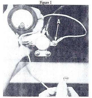
There should be a solenoid, usually mounted on the firewall near the pump. To determine if current is reaching the circuit breaker, connect the positive lead of a tester to the power source terminal “A” of the circuit breaker and the negative lead to a good ground, as shown in Figure 1 on the next page. A current flow should register on the tester. If not, check the wire from the power source for a break or a short. In some cases, failure of the hydraulic motor to start may be caused by an inoperative motor solenoid switch.

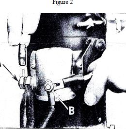
To check the operation of this solenoid, connect one end of a jumper wire to the battery wire terminal “A” and the other end to the switch wire, terminal “B,” as shown below in Figure 2. If the switch is operating satisfactorily a “click” will be heard and the battery to motor circuit will be closed, starting the motor. If no “click” is heard, the solenoid should be replaced.

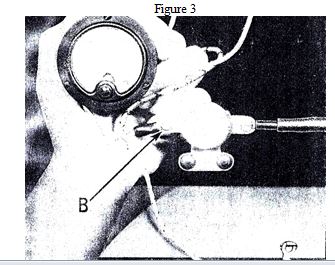
Next, to determine if the circuit breaker is operating, connect the positive lead of the tester to the switch feed wire terminal “B” of the circuit breaker and ground the negative lead, as shown below in Figure 3.
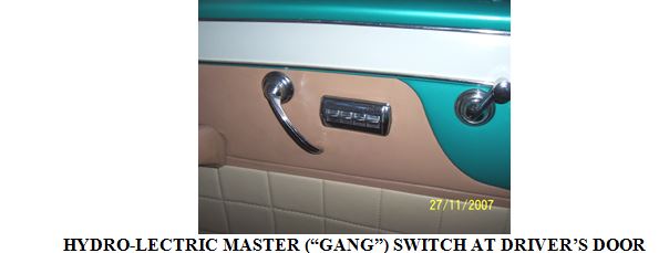
A current flow should register if the circuit breaker is operating. Sometimes, the power window, or power seat, switch may be at fault. On the back of the switch, using an individual window switch as an example, will be three terminals. These terminals will be marked “BAT” (battery), “MOT” (motor), and “CYL” (cylinder). The center terminal is typically the “battery,” or feed, terminal. You can test the operation of the switch by disconnecting the wires and using a simple ohmmeter. Place the 2 leads of the ohmmeter between the “BAT” and “MOT” terminals and push the toggle switch in the upwards position. If the switch is okay, you should get a reading on the ohmmeter. Use the same procedure to check for continuity between the “BAT” and the “CYL” terminals. Another simple way of testing the switch, with all wires connected, is to place a jumper wire between the “BAT” and “MOT” terminals. If the circuit and switch are okay, the hydraulic motor should start. When placing the jumper wire between the “BAT” and “CYL” terminals, you should hear a distinctive “click”, which is the cylinder solenoid operating.
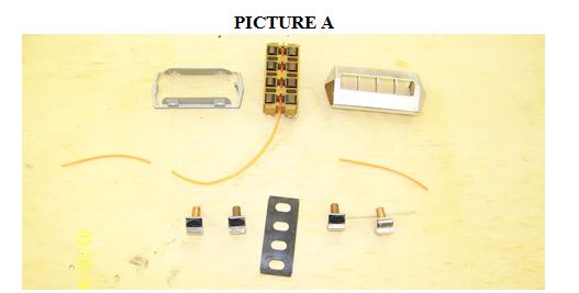
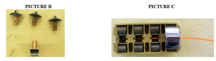
As with most everything made in “the good old days,” these switches can be disassembled for cleaning or repair. They are basically a toggle with return springs and copper contacts. If the spring(s) or toggle assembly are not broken, you can usually restore these switches to operating condition simply by cleaning the copper contacts using 600 grit wet/dry silicon carbide sandpaper or a good commercial electrical contact cleaner.
In addition to the electrical system, it is imperative that all windows, power seat, and convertible top mechanisms operate freely by hand with no binding or obstructions. Clean and lubricate (I use white lithium grease) all pivot points on the frameworks containing the hydraulic cylinders, seat tracks on power seats, and pivot points on the convertible top. Inspect the mohair-lined U-shaped channels in which the window glass rides and replace if worn or damaged.
Finally, on convertibles only, there is an additional component I refer to as the power top control switch. This is a Bakelite unit mounted on the firewall with two wires attached to terminals, and fittings with metal lines attached. The top portion of this switch is attached to the “power top” operating knob and lever, which goes through the firewall and is attached to the bottom of the dash with a mounting bracket. When you “PULL” this rod, it rotates the top portion of the Bakelite unit. Inside this unit are return springs, a circular copper contact plate, and ports. When you “PULL” or “PUSH” the power top control rod, the upper portion of the Bakelite switch rotates, completing the electrical circuit and starting the hydraulic motor. At the same time, the appropriate ports inside the unit are uncovered, thus diverting the fluid to either raise, or lower, the top. This Bakelite switch can also be disassembled for cleaning, and can usually be restored to operating condition as long as the Bakelite housing isn’t broken.
So there you have it. What seems like a complicated system is actually quite simple when broken down into its individual components. New cylinders, hoses, Hydro-lectric motor and top control switch rebuilding, and expert technical advice are readily available from Hydro-E-Lectric in Punta Gorda, Florida by calling (800)343-4261. They are very knowledgeable and wonderful people to deal with!

jun 12 hy 1

jun 12 hy2

jun 12 hy3

newsletter

THE INFAMOUS HYDRO-LECTRIC SYSTEM PART I

Mention Hydro-lectric system to anyone who even knows what they are and you’ll get mixed reactions; mostly negative. It’s not that these systems didn’t work well; in fact, I’ve seen some that work as well, if not better, than a “modern” system! The problem(s) arise from lack of proper maintenance, long periods of storage, or a combination. My first experience with Hydro-lectric systems was in 1989 when I undertook the restoration of a very rough 1948 Cadillac convertible. The entire system on the car needed rebuilding, as the vehicle had been in storage for many years and time took its toll. After many hours of labor, an endless litany of expletives I can’t repeat here, and a serious cash outlay, I found, much to my astonishment and satisfaction that everything actually worked! In fact, the gentleman who bought the car in 1990 reports that the system still performs flawlessly!

Cadillac, various other GM makes, and other car manufacturers had been using the Hydro-lectric system since the early 1940s. At least in 1949, which I’m most familiar with, the system was standard equipment on the 60 Special, convertible, Coupe De Ville, and some models in the 75 series. It was an extra-cost option on the Series 62 sedans and coupes, but since it was rather “pricey” at $121.65, few Series 62 buyers opted for it. The system was used until 1953, when electric power windows appeared on all vehicles.

The Hydro-lectric system was revolutionary when it was introduced, and a veritable marvel of engineering, especially considering it was designed and executed way before the days of CAD (Computer Assisted Drafting). It’s also an extremely ingenious system that with proper maintenance could, and would, operate satisfactorily for years. Essentially, the system consists of a pump, typically mounted on the fire-wall, electrical switches, hydraulic cylinders mounted in pivoting frames with a large spring or springs, a closed loop of metal lines and rubber hoses, and a wiring harness. It powered the windows, the front seat and, on convertibles, the top.

The Achilles’ Heel of this system was the use of brake fluid as a medium. Since brake fluid starts attracting/ developing moisture the moment the bottle is opened, after years of inactivity it coagulates into a pasty, sometimes rock-hard consistency, clogging the lines and seizing up the pump and cylinders. This necessitates a rebuild of the pump and replacement of the cylinders; not an inexpensive proposition! This is why, in the owner’s manual, it’s stressed that all power equipment (seat, windows and top) be operated at least once monthly to “keep things flowing.”

Here are the principles of operation: the Hydro-lectric pump, comprising a motor resembling a starter, a housing containing two “rotors” in a cavity which pump the fluid, an electrical solenoid, and a reservoir at the bottom portion to hold the fluid, is mounted vertically on the firewall with three rubber “cushions.” Also mounted on the firewall, near the pump, is a circuit breaker to protect the wiring from overload or shorts in the circuit. A rubber hose (or two hoses if it’s a convertible) runs from the pump to a network of metal tubing and additional rubber hoses that go to the power seat, windows, and convertible top. Inside each door is a metal frame containing a hydraulic cylinder held in place with special clips, and either one or two very strong springs. The upper part of the frame has scissor-like arms which attach to the window channel. In each door pillar is a rubber hose which allows flex when the doors are opened and closed. On convertibles, two metal lines, with loops in them to allow for movement, are attached directly to the large cylinders that operate the top. One line goes into the top of each cylinder, the other to the bottom, so that the cylinder piston rod can either extend or retract, thereby raising or lowering the top.
A “gang” or master switch, containing four individual switches, is mounted on the driver’s side front door panel. This is used to control the four windows. When a window switch is pushed upwards, the circuit is completed, powering the motor on the pump, which then pumps fluid to the appropriate cylinder and raises the window. When the window switch is pushed downwards, an electrical solenoid at the bottom of the cylinder is activated, and a valve opens. The springs then gently, and quietly, pull the window down, forcing the fluid out of the cylinder, through the lines, and back to the pump reservoir. The power seat, which operates similarly, has its own switch.

HYDRO-LECTRIC MASTER (“GANG”) SWITCH AT DRIVER’S DOOR

On convertibles, an actuating rod with a knob labeled “power top” goes through the firewall and is attached to a Bakelite power top control valve. This is essentially an electrical switch and valve unit. When the power top rod is pushed in, or pulled out, the top portion of this unit rotates. Inside the unit is a spring which returns the rotating part to its “neutral” position, and circular copper strips. When the power top rod is pulled or pushed, the rotating portion will swivel, thereby completing the circuit and actuating the pump. As the top portion of the control valve is rotated, it also opens one of two ports, diverting the fluid either to the bottom part of the top cylinder, thereby raising the top, or to the upper part of the cylinder, lowering the top.

Sounds simple, doesn’t it? In the next installment, I’ll get into the more technical aspects of this system, such as the wiring of the switches, rebuilding the system, and troubleshooting techniques.

hydro 1 dec 11hyydro 2 dec 11

hydro 3 dec 11

hydro 4 dec 11

newsletter

POWER WINDOW SWITCHES AGAIN

This is what I do to repair the Hydro Electric Window Switches when they start to act up. A lot of time, the nylon rod breaks from age and use. This makes the switches sloppy and prone to poor contact. This angers the driver when the windows sometimes fail to go up, or sometimes fail to go down. Removing the switch for the car is not terribly difficult – just be sure to mark the wires so you know where they go. If the wiring is original, be careful about handling it or you may have to use shrink wrap insulation if the cloth insulation comes off.

The pictures show the refurbishment of a 1953 Cadillac 4-gang switch, but the 1949 switch is the same as in all functional respects; only the chrome is a little different. Picture A shows a 4-gang switch disassembled. The orange wire or rod is weed wacker line, .095” in diameter. I have also used the tip off a broken fly rod instead, but finding broken fly rods is not easy!

windows sw sep 10 1

PICTURE A

The most difficult part of disassembly is getting the spring clip/lock off (Picture A, top left) without damaging it or the housing. But if one is patient, one can get the two spring clips out of their holes and slide it off. Then everything just falls apart.

Picture B shows the toggles from two different perspectives, one with a nylon rod through it and three oriented to show the holes in the toggles for the nylon rod. It goes through all 4 toggles and holds them in place and ensures good contact on the spring surfaces. Both ends of the original nylon rod are tapered, but the weed wacker line will fit fine without the taper. If you have trouble threading it in, you could taper one end of the replacement line (rod) with a little sandpaper. These toggles are original to a 1949 Cadillac.

windows sw sep 10 2

PICTURE B PICTURE C

Picture C shows the base unit with one toggle installed and the orange nylon line partially installed. It takes a little patience to install the line, but really it is not that bad of a job. Red wine is a great shop assistant!

While you have the switch assembly apart, now is a good time to clean and polish things. Take time to clean up the housing. Also, take the springs out and polish them for better electrical contact. I generally clean them up just in case. A dab of dielectric grease might be used to maintain good electrical contact and avoid corrosion down the road.

When you get the toggles installed and the rod threaded the spring clip fits over the hole where the rod goes through. The clips hold the rod in place. Once done the switch toggles will be nice and tight and work a lot better.

newsletter