
Category Archives: Horn
CHECK YOUR HORN RELAY IF THE HORN DOESN’T BLOW
The horn relay is the small black box with 3 wires connected to it on the upper driver’s side of the ’49 firewall. They are inexpensive and easily obtained, as the same horn relay was used on 1934-52 Cadillacs and probably other GM cars as well. You can merely replace it and see if this corrects the problem. If you prefer testing it first, have an assistant press your horn button. Assuming the horn does not blow, connect a jumper wire from the center terminal of the relay to the left hand terminal; that is, the terminal closest to the center of the car. If the horn then blows, the problem may be with the relay.
newsletter
COME BLOW YOUR HORN
by Art Gardner
Installing my 6107’s horns was one of the last tasks to complete after getting her running. I hooked up the wires to the horns, relay, etc and tried out them out. They blew for a second or two and then quit. So I had to take the horns off and give them a “tune up” by taking them apart, filing the points (using an ignition points file), cleaning them up internally, adjusting the points to give a consistent tone, painting, etc.
The task of adjusting the points is a bit irksome, as it will annoy the neighbors! Basically, you turn the adjustment nut while energizing the horn with a couple of wires until a good sound comes out of the horn. After reinstalling the horns, all that was left was to install the horn button and horn ring. That job took a little bit of patience in order to make the system work reliably, as described next.
To get the horn ring and button working right, I first had to adjust the longitudinal position of the steering shaft relative to the steering column. This was because I had changed this positioning inadvertently as part of the installation of a rack and pinion steering unit. This is not necessary on cars with stock steering.
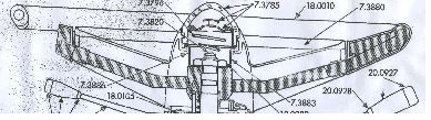
Next came the task of trying to find the right replacement for the fiber washer that originally was fitted under the little contact at the top of the steering shaft. As you can see in the schematic below of a generic Cadillac steering wheel, the horn button (7.3785) is held away from the steering shaft by a conical spring (7.3796) which rests at its small end against the nub of the contact (7.3820).
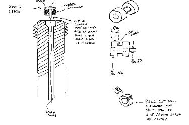
The contact has a flange and a shank (not seen in this parts diagram). I thought that the horns were energized by the flange of the contact touching the top of the steering shaft. But that is not the usual manner of blowing the horn. Instead, the flange is held slightly away from the top of the steering shaft by the washer, even against the force of the horn button spring. When the horn ring is pushed, it causes the contact to tilt slightly in the same direction as the horn ring. The lower tip of the contact apparently then touches the inner wall of the steering shaft, completing the circuit. See my sketch (not to scale and a little rough, but you will get the idea). The trick then is to come up with a decent replacement for the washer that will be thick enough to keep the flange from contacting the top surface of the shaft and yet will allow the horn to blow when the horn ring is tilted. Jay Friedman told me that some folks take a small rubber band and wrap it around and around the shank to make a replacement. I tried that, with poor results. The car had an O-ring on there as some previous owner’s attempt at a repair, but it wasn’t doing the job.


What I came up with is a bit of rubber grommet as shown in the drawing above. I cut the grommet with a scissors to make a suitable collar to wrap around the upper part of the shank of the contact. To slip it over the shank without removing the horn wire from the shaft, I simply sliced it lengthwise (split it) with the scissors. Since it is captured in the bore, the split in the rubber is of no consequence. I found that a grommet with a 3/16″ ID worked well. Alternatively, a bit of rubber hose with a similar diameter would work as well. It takes some careful trial and error to get the length of the rubber /grommet just right, but I managed in 4 attempts. The set up works well and my car has working horns for the 1st time in 2 decades
COME BLOW YOUR HORN
by Art Gardner
Installing my 6107’s horns was one of the last tasks to complete after getting her running. I hooked up the wires to the horns, relay, etc and tried out them out. They blew for a second or two and then quit. So I had to take the horns off and give them a “tune up” by taking them apart, filing the points (using an ignition points file), cleaning them up internally, adjusting the points to give a consistent tone, painting, etc.
The task of adjusting the points is a bit irksome, as it will annoy the neighbors! Basically, you turn the adjustment nut while energizing the horn with a couple of wires until a good sound comes out of the horn. After reinstalling the horns, all that was left was to install the horn button and horn ring. That job took a little bit of patience in order to make the system work reliably, as described next.
To get the horn ring and button working right, I first had to adjust the longitudinal position of the steering shaft relative to the steering column. This was because I had changed this positioning inadvertently as part of the installation of a rack and pinion steering unit. This is not necessary on cars with stock steering.
Next came the task of trying to find the right replacement for the fiber washer that originally was fitted under the little contact at the top of the steering shaft. As you can see in the schematic below of a generic Cadillac steering wheel, the horn button (7.3785) is held away from the steering shaft by a conical spring (7.3796) which rests at its small end against the nub of the contact (7.3820).
The contact has a flange and a shank (not seen in this parts diagram). I thought that the horns were energized by the flange of the contact touching the top of the steering shaft. But that is not the usual manner of blowing the horn. Instead, the flange is held slightly away from the top of the steering shaft by the washer, even against the force of the horn button spring. When the horn ring is pushed, it causes the contact to tilt slightly in the same direction as the horn ring. The lower tip of the contact apparently then touches the inner wall of the steering shaft, completing the circuit. See my sketch (not to scale and a little rough, but you will get the idea). The trick then is to come up with a decent replacement for the washer that will be thick enough to keep the flange from contacting the top surface of the shaft and yet will allow the horn to blow when the horn ring is tilted. Jay Friedman told me that some folks take a small rubber band and wrap it around and around the shank to make a replacement. I tried that, with poor results. The car had an O-ring on there as some previous owner’s attempt at a repair, but it wasn’t doing the job.
What I came up with is a bit of rubber grommet as shown in the drawing above. I cut the grommet with a scissors to make a suitable collar to wrap around the upper part of the shank of the contact. To slip it over the shank without removing the horn wire from the shaft, I simply sliced it lengthwise (split it) with the scissors. Since it is captured in the bore, the split in the rubber is of no consequence. I found that a grommet with a 3/16″ ID worked well. Alternatively, a bit of rubber hose with a similar diameter would work as well. It takes some careful trial and error to get the length of the rubber /grommet just right, but I managed in 4 attempts. The set up works well and my car has working horns for the 1st time in 2 decades
If Your Horn Doesn’t Work
If Your Horn Doesn’t Work