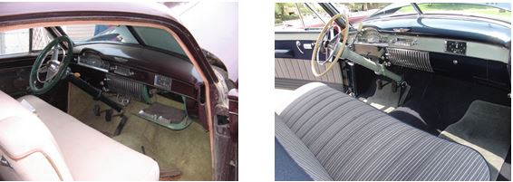
INTERIORS OF TWO ‘49s WITH STICK SHIFT. THE FIRST IS A 6107 IN “BEFORE” (RESTORATION) CONDITION THAT ROBERT ROBIN CHECKED OUT (BUT DID NOT BUY) AT AN ESTATE SALE.
THE SECOND IS AN “AFTER” PHOTO OF JIM JORDAN’S GORGEOUS COUPE DE VILLE.
INTERIORS OF TWO ‘49s WITH STICK SHIFT. THE FIRST IS A 6107 IN “BEFORE” (RESTORATION) CONDITION THAT ROBERT ROBIN CHECKED OUT (BUT DID NOT BUY) AT AN ESTATE SALE.
THE SECOND IS AN “AFTER” PHOTO OF JIM JORDAN’S GORGEOUS COUPE DE VILLE.
Does your shift lever loosely flop from front to back rather than spring toward the front of the car when you remove your hand from it? Maybe your lever is “sloppy” from side to side, too. If so, and your ’49 is not one of the 11 belonging to chapter members with stick shift (as the s lever is different), read on.
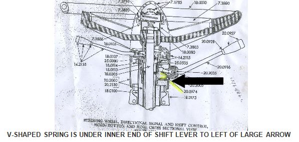
As shown in the drawing below of a similar 1955 Cadillac steering column, the back-to-front position of the Hydra-matic shift lever is controlled by a flat V-shaped spring inside the steering column just under the inner end of the shift lever.
Occasionally, these springs simply snap in two, allowing the lever to merely flop. While you can still shift between N, Dr. Lo and R, it can be very annoying to the driver as it just won’t feel quite right. I recently helped Art Gardner and Frank Lindauer, Times Editor and Editor Emeritus, respectively, install new springs in their steering columns and feel it would be useful to summarize how it was done.
1. Get a new spring. Occasionally, they are offered for sale on Ebay, where Frank got his for $15 or so. Another source is CLC member Joe Alcorn, 111 W. Park Blvd., Westmont NJ 08108-3345, phone:
856-858-8899, who apparently has a stock of them.
2. Disconnect a battery cable so the unwanted sound of your horn doesn’t drive you and anyone else to distraction. Next, remove the horn button by holding the horn ring toward you with one hand, while simultaneously pressing in and turning the button counter-clockwise about 1/3 of a turn to release it. Note that the big end of the cone-shaped spring under the button is toward you. Remove the spring.
3. Remove the large nut that fastens the steering wheel and horn ring to the steering column. Lift off the horn ring assembly. Make two small adjacent witness marks with a punch on the splined steering wheel hub and the steering column shaft so that you replace the steering wheel in the same position when the job is done. Using a steering wheel puller, remove the steering wheel.
4. You have now exposed the innards of the directional signal housing. Looking into it, you will see four Phillips screws that hold the housing to the steering column. As these screws are recessed behind part of the housing and can’t be reached with your fingers, it is best to remove them with a magnetic screw driver. If you don’t have one, you may drop the screws inside the housing after unscrewing them, so keep handy a mechanic’s magnet and a pair of small tweezers to retrieve them.
5. Once the screws are removed, you must pull the doughnut-shaped directional signal housing and the cable attached to it toward you and around the top of the steering column shaft to expose the shift lever housing underneath. You may find that the directional signal cable is too short to allow the housing to be pulled sufficiently toward you and you can’t get it around the top of the steering column shaft. If so, don’t lose your cool, but reach down under the dashboard to the point on the steering column where the directional signal cables enter the column and carefully push them further into the steering column. After playing around with the cables a bit under the dash you should free them up enough at their upper end to be able pull the housing around the top of the steering column shaft and set it to one side.
6. Now, you must remove the shift lever. First, unscrew the chrome cup at the inner end of the lever from the steering column. In doing so you will expose a tapered hinge pin upon which the lever pivots. Using a small punch or Phillips screwdriver, gently tap the pin up from bottom to top (it can only go one way). Remove the pin and pull out the lever. As you remove the lever, note and collect the little anti-rattle springs that flank the lever, if they are present.
7. You should now be able to see the broken parts of the V-shaped spring that you will replace. Pull these out with tweezers. The new spring must be installed with the two V arms facing toward the inside of the steering column. (See diagram above.) You may have to manipulate it a bit and even tap it in with a small punch and hammer. Now, lightly grease the spring, the shift lever and hinge pin, then re-install the lever over the top leaf of the spring. Re-install everything else in reverse order and you are done.
NOTE: the large nut that fastens the steering wheel and horn ring to the steering column must be torqued to 45-50 foot-pounds. Hold the torque wrench in one hand and the rim of the steering wheel with the other.
In June 2005 I purchased a ‘49 Coupe De Ville sight unseen on EBay. The car was located south of Houston, Texas, and since I live in Ontario, Canada I had it delivered to my friend Simon who lives in nearby Seabrook TX. I had asked Simon to check out the brakes, steering and general condition of the car. The report came back favorable, so my wife, Kathy, and I decided to fly down from Buffalo NY and drive it home.
When we arrived in Texas we put a few shake-down miles on the car and discovered that the rear end was getting noisy–oh,oh! We agreed that we could not ignore this and pulled the axles so we could remove the differential carrier. We discovered that whoever had replaced the seal had not torqued the pinion nut properly. We re-torqued it to the required 200 ft. lbs., re-assembled and the noise was gone. Kathy insisted that she wasn’t going anywhere without seatbelts, so we put them in the front.
The engine ran well and the car started, stopped and steered well. The Hydra-matic transmission, however, would not shift properly. It would stay in 1st too long, then skip second and move swiftly thru 3rd and into 4th. It also would not downshift unless shifted manually. If held in Lo it would eventually shift into 2nd. We drove it home some 1,750 miles through Buffalo to Beamsville, Ontario. Along the way we stopped in Chattanooga, TN to get a set of Coker BF Goodrich WW radial tires. Boy, what an improvement in ride that made. The car no longer wandered the road grooves and I found myself driving faster.
We did have a mishap on a bumpy freeway in Ohio. The right rear sombrero wheel disc flew off, taking the fender skirt with it. We pulled over and managed to collect both items. The wheel disc was destroyed, but the skirt had only minor scrapes. Checking out the wheel disc once we were home, I found that it was a pre-48 style disc and therefore it did not engage onto the wheel clips far enough to be held secure. We crossed the border without any hassles and brought the car home.
We were busy building a house and shop for the next few years so I did not have time to work on the Coupe De Ville. Finally this summer it was time to do something, so I read section 13 of the ’49 shop manual and put the car up on ramps to adjust the transmission linkage. Part of the reason I hadn’t got to it earlier was that the manual shows a Throttle Lever Checking Gauge that I did not have. I knew that correct linkage adjustment is critical for the transmission the shift properly. Well, I would just have to make do without a gauge and try different adjustments. I disconnected the throttle control linkage from the throttle valve lever, as per fig.149 on page 149, and moved the lever forward and back to find the limits of movement or rotation. To my surprise I could not feel a stop position when moved in either direction. This led me to believe that though the throttle rod lever was moving externally, nothing was moving internally.
I drained 2 quarts of transmission fluid, removed the manual control lever, throttle control lever, and side cover. I then very carefully removed the outer valve body since it houses the inner throttle lever shaft. Before removing the valve body I lifted the car’s carpet and removed the center floor pan with the accelerator pedal so I could see exactly what I was doing and hopefully not drop any parts.
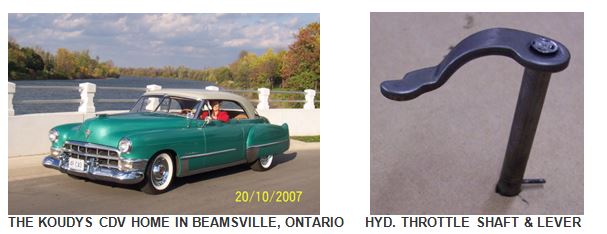
The throttle shaft, shown in Figure 198 on page 175 of the shop manual and in the photo below, has a lever pressed onto it. The shaft has a straight knurl and the end is peened to fix the inner lever to it by an interference fit. The fit had loosened so when the shaft rotated the lever did not move. I brazed the stamped lever to the shaft after indexing it to the proper location. I had a spare shaft to verify the proper location. This spare shaft’s lever had also become loose but had not slipped yet.
I assembled everything, replenished the oil and went for a drive. It shifted into second gear before I reached the end of the driveway, so a big grin appeared and I knew I had solved the problem. I now take every opportunity I can to drive the car as it’s such a pleasure to drive.
More On Those Other 49 Cadillacs
Those Other 1949 Cadillacs Or Stick Shift’s Last Hurrah