Category Archives: Interior

Heater Removal and Rebuilding

Thanks to Fab for posting this on the CLC forum

just rebuilt my entire heater system about 3 or 4 months ago. To remove it, you need to do the following:

1. Unhook the electrical connections under the dash. I think there are only two wires, a fused power source, and a wire to your underseat heaters.

2. Detach the two control levers.

3. Unscrew the metal bracket holding the thin copper capillary tube in place.**

4. In the engine compartment, remove the heater hoses from the bottom of the unit.

5. Remove all the bolts attaching the unit to your firewall. There’s a rubber gasket between the heater unit and the firewall. Mine had somehow sealed the unit to the firewall, so I had to pry it off. (You can buy a replacement here: http://www.steelerubber.com/heater-gasket-70-0448-31)

6. Once you get everything removed and the unit free, start to pull it out gently. You’ll see a vent cable attached to the side of it. Unscrew and release this.

**MOST IMPORTANT THING: make sure not to pinch or break the thin copper capillary tube. If you damage this, your heater valve will be useless. Best to have somebody on the inside helping guide the unit out.

Once you get the unit out, you can remove the two heater valves. I sent mine to Jim Tucker: http://www.heatercontrolvalve.com/. I think it was about $250 to rebuild both valves.

Lily Restoration Series 60

Jon Yinger passed along this video of his series 60 Lily undergoing a complete restoration finishing with a mild custom. There are some nice still of the engine compartment both before and after the restoration. He has a nice shot at the end with it cruising down the road. He also passed along a link to the rest of the cars in his collection.

I am going to add another category for videos on the right hand side to make these easier to find. I will try to categorize these as much as possible but some will just be eye candy.

AN ENTIRE DASH IN THE PROCESS OF BEING REMOVED FROM A 49

In the photo, the following has been done so far: 1. The vent control knob and bracket have been unfastened from the dash; 2. The hand brake handle bracket has been unbolted; 3. The windshield wiper-washer switch and the fog light switch have been removed; 4. The instrument panel has been removed, with a piece of cloth protecting the steering column from being scratched by the instrument panel as it is withdrawn from the dash; 5. The molding has been removed from the bottom of the windshield and the top of dash to expose the screws holding the dash to the cowl.
The following is still to be done: 1. The radio must be removed; 2. The steering column bracket holding the steering column to the dash must be removed. 3. The head light switch must be removed. 4. The wiring harness must be disconnected. (Note the Allen wrench in the nut holding the head light switch to the dash after the switch knob has been removed).

AND OFF IT COMES, A PIECE OF CAKE!
dec 12 dash1

dec 12 dash2

newsletter

STOP PLEASE DON’T CHOP THAT CADILLAC OR ARE YOUR DESIGN SKILLS REALLY BETTER THAN HARLEY EARLS

by Art Gardner

I have had ten 1949-56 Cadillac’s over the last 25 years. Some I kept bone stock, one I highly modified, and to several I made minor “tweaks” to improve performance/reliability/safety/convenience. From my experience, I encourage you to consider keeping your ’49 or any other old Cadillac completely stock or very stock — for financial, aesthetic, and enjoyment reasons. Don’t do something you will regret later, as there are many hidden dangers and pitfalls in modifying old Cadillac’s.
To me, the biggest drawback is that most people are not as skilled at car design as the original designers (no surprise there) and the car is likely to end up looking and performing much worse than the original. Secondly, it is often a financial disaster to make big changes to a ’49 or other old Cadillac. Many people start down a path of “customizing” a classic car by chopping the top, frenching the headlights, shaving the door handles and other exterior chrome, adding louvers, replacing the engine with a generic Chevy 350, etc. Most of the time this ends up ruining the car permanently. Do you really think you can make a classic Cadillac more beautiful than did the original designers? Perhaps, but most such modifications rob the car of its intrinsic appeal and make it uglier, not prettier. Sometimes the car does end up looking good. But often not.
I strongly recommend retaining the original drive train, as the 331 Cadillac engine is very, very good – in fact it was at the top of the heap for decades and is just as mechanically reliable as any small block Chevy. Same thing for the our HydraMatic transmission. It is just about bullet-proof. If yours doesn’t work like it should or if it leaks, get it professionally rebuilt and enjoy years of trouble-free automatic shifting.
Without going into all of the gory details, here are my bottom-line recommendations, learned the hard way, for what works well on a 1949 Cadillac:
1. If it came with 6 volts, keep it 6 volts if possible. Pay attention to grounds and the proper cables. Six volts works!
2. If you must improve the electrics, use a 6 volt alternator (keeping the voltage regulator in place for looks).
3. On a ’49, just a “sample” of the current goes through the ammeter, so keep the ammeter as is.
4. Use a better battery (I like the 6v Optima a lot).
5. Add air conditioning if you have to in order to use the car (in which case you would have to convert the car to 12 volts). Otherwise, don’t.
6. Use stainless steel brake lines (to resist internal corrosion) and dual circuit master cylinders for redundant safety. If sticking with a single circuit master, have it sleeved with brass or stainless steel to stop internal corrosion. If you can afford it, have the wheel cylinders sleeved with brass or stainless steel also. Use a remote brake reservoir (you can use parts from a ’54 and later Cadillac) to allow you to check the fluid regularly.
7. Convert your non-functioning clock to a quartz movement.
8. Use an electronic ignition module (e.g., Pertronix) or a dual point distributor plate for better ignition.
9. Keep the exhaust stock, but increase the pipe size slightly to a 2¼ inches diameter for better breathing.
10. Keep the fuel system stock. If vapor lock or engine overheating is a problem, use an electric fuel pump for “go” and keep the mechanical pump just for “show” (remove the rod and route the fuel through the non-working mechanical pump).
11. Avoid adding power steering; but if you must, use a later Cadillac system. Avoid rack and pinion.
12. Use radial tires. If your car doesn’t have power steering, look for radials with a very narrow contact patch (e.g., the Diamondback 700R15) and run the recommended higher inflation air pressure.
13. Keep your stock radio, but have it rebuilt. Rebuilders can add an MP3 input to the radio to play FM and digital music files.
14. Add seat belts, which can be easily done. On 4-door sedans and Series 75 limos, you should add shoulder belts.
15. Install a thicker stabilizer bar up front (like the’49 limos and hearses have) – you will be glad you did and no one will know.
16. Stick with the vacuum wipers if you can. If not, enjoy your electric wipers!

If you follow this advice, you will love using your car and will find that you drive it more and more. Above all, my cardinal rule is that if you feel compelled to change something, please change it in a way that can be undone easily (keep the original parts if you can and make the change a bolt-on operation). In other words, make the change a reversible one! Also, if possible, try to make the change look like it came that way from the factory. For example, if you are replacing the generator with an alternator, don’t use a chrome-plated alternator that will look terribly out of place in a 1949 Cadillac engine bay. Instead, get one that is black or paint it black to fit in with the rest of the engine bay.
In the end, it is your car, not mine, so do what makes you happy. But if you do want to tweak your car some, you will be miles ahead if you learn from my mistakes and triumphs. If you have specific questions about any of this, feel free to contact me

newsletter

A BETTER WAY TO REMOVE YOUR STEERING WHEEL

by Art Gardner

If, like lots of us, you don’t have a steering wheel puller, I’ve come up with another, if not better, way to remove your steering wheel.  Besides doing away with the need for a puller, this method spares the horn button contact from possible damage.


Refer to the drawing below, which shows the top of the steering wheel after the horn button is removed.  First, remove the large nut which holds the wheel.  Using a small diameter round file (no, not the trash can), file “half-moon” slots into the middle of two opposite sides of the nut to line up with the threaded holes in the hub of the steering wheel.

Now, refer to the drawing on the next page.  Go to a hardware store or other supplier of fasteners which sells 3/8-16 “washer-head” bolts, sometimes referred to as washer-head screws.  (These are bolts or screws with an integral built-in washer as part of the bolt head.)  I suggest that you buy 6 such bolts: 3 pairs or 2 each, in lengths of ¾ inch, 7/8 inch and 1 inch (1.9, 2.2 and 2.5 cm.), if available.  You can see two of them in the drawing.

As shown in the drawing below, loosely screw on the large steering wheel hold-down nut the until most or all of its threads have engaged the steering shaft, but with some space still remaining between the bottom of the nut and the steering wheel hub.  At the same time, make sure the two “half-moon” slots are lined up with the threaded holes in the steering wheel hub.  Then, starting with the 1 inch pair, screw two of the washer-head bolts past the “half-moon” slots and into the threaded holes in the steering wheel hub until the washer heads are snug against the large steering wheel nut.


Now, using a wrench, slowly and carefully tighten the washer-head bolts, each one a fraction of a turn at a time, so that neither bolt puts more pressure on the nut than the other.  Advantageously, this works by putting force on the large threads of the steering column shaft, instead of on the end of the shaft (where it could damage the horn contact).


As I did, you may find that you will have to exchange the first pair of washer-head bolts for a shorter pair as the steering wheel is pulled up.  You may also find that you’ll have to unscrew the large steering wheel nut one or more turns to create more space between it and the steering wheel hub.  When the steering wheel breaks loose, you may or may not hear a snapping or popping noise.   Like the 3 guys lowering the engine in the factory photo on page 3, “Easy does it”

steerin dec 10

steerin 2 dec 10


newsletter

MORE ON HOOKING UP HEATER HOSES

Chapter member Daniel Parker of Palmdale, California sent in the diagram below and wrote that he thought it “might help the next time someone asks how to route heater hoses”. To aid in using Daniel’s diagram, members may want to refer to the June ’09 issue of the Times, in which there appeared an article describing in text the routing of these hoses.

dec 10 heater


dec 10 heater 2

newsletter

SERVICING THE 1949 CADILLAC SPEEDOMETER HEAD

Recently the speedometer head on my ’49 Coupe de Ville developed a screeching noise that was loud and about as welcome as fingernails scratching a chalk board. If you follow the steps listed below you can fix your speedometer, also.

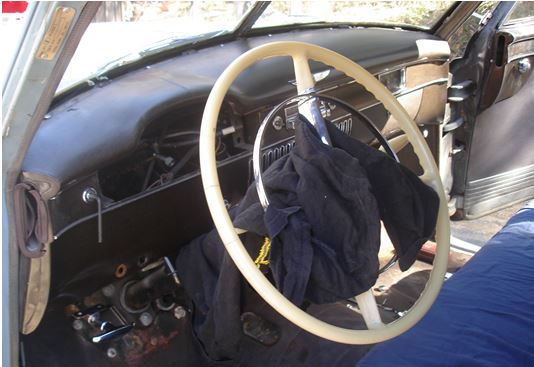
Disconnect the ground cable from the battery. Wrap a towel around the steering column and secure it with tape. Apply tape to towel, not the paint. Lie underneath the dash with a good light. Remove the 2 wing nuts that secure the instrument cluster to the dashboard. Loosen the nut at the bottom of the dash for the trip odometer. Make sure there is enough slack in the oil pressure tubing to allow the cluster to move forward a couple of inches; if not, disconnect the oil pressure tube now. Push and wiggle the instrument cluster toward steering wheel about two inches. Be patient. It’s been there for 60 years and it may want to stick. Return to sitting position in your front seat. Your back will appreciate this. Now you can lean forward and view the backside of the entire cluster. You can also pull the cluster a little closer to your body to have easier access to everything connected to it.

You MUST mark all wires and bulb fixtures BEFORE unplugging them from the instrument cluster housing. I recommend using masking tape on each wire, numbering everything from left to right and writing those numbers down. Unplug all wires from the gauges, all bulb fixtures, and unscrew the speedometer cable nut and pull cable out. You must also remove the oil pressure gauge tubing. Use caution. Use an open end wrench to secure the gauge fitting as you loosen the tubing fitting so as not to damage the gauge. A 6 point tubing wrench is best for the tubing nut. Do not damage the nut. Unscrew the odometer reset cable at the speedometer housing and pull it out. With everything disconnected you can remove the entire cluster from the dash, while taking care not to bump any painted surfaces, and place it on your workbench face down against a soft cloth.

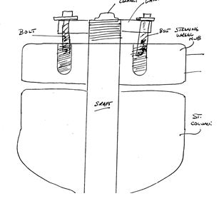
Remove the 2 screws that go through the rubber grommets near the connection for the speedometer cable. Keep all screws and fasteners in a shallow pan or other suitable container since you don’t want to lose anything! Remove 4 screws that hold the galvanized cover to the speedometer head. Gently place a thin screwdriver between the cover and main housing and pry it away from the head AS you hold the head downward. It may stick because there is a rubber gasket between the cover and head. SAVE the rubber gasket and grommets. Now you will be able to view the speedometer head. It is a delicate instrument so be careful handling it! You will see 2 tabs about an inch long that are bent over the edge of the head to secure it during assembly at the factory. Bend them sideways just enough to allow sufficient clearance for the head to be lifted out of the main housing.

Before lifting the speedometer head out of the main housing REMIND yourself that you do not want to damage the pointer or the very delicate spring that is attached to the rotating part that attaches by a slender shaft to the pointer. Lift the head out of the main housing and place it on your work bench with the pointer side (front) facing your body. Write down the orientation of the indicator needle/pointer in relation to the left directional signal arrow. When reassembling you will want to place it back onto the shaft in the SAME position. Use two thin bladed screw drivers to get underneath the pointer. The ends of the screw driver blades should contact the shaft and be opposite one another so when you pry the pointer upward you do not break it. It does not require much strength, but you MUST pry with equal pressure. After you have removed the pointer you will see that it has internal splines that mate to the splines on the shaft. That’s why you marked the orientation prior to removal.

Remove the 2 screws that secure the plated face, with directional arrows, to the head’s pot metal housing and lift the face off. Your next step is to remove the 2 countersunk screws that secure the support for the shaft. After you have removed the support, the shaft will develop a mind of its own and flop all over the place, so handle with care. You do not want to damage the spring. As you handle the head for continued disassembly the part that rotates with the shaft may get out of its correct position. Just remember that the stops rest against each other so as to prevent the indicator needle from rotating too far counter-clockwise. When reassembled the needle must rotate clockwise to indicate the speed you are traveling.

Next you will find one thin clip that secures the numbered speedometer assembly and one that secures the numbered odometer assembly. Remove the clips one at a time and remove the numbered assemblies one at a time by sliding them in the direction of the retaining clip groove as you lift out the opposite end and then slide it back toward the original position. Put differently, they angle out of the housing. Please note: the back side of the numbered assemblies have slotted tabs that must engage a thin flat strap to correctly orient them. Visually examine before removing. Now you can remove the gear that runs front to back in the housing. Note orientation. Don’t attempt to remove the other gears. Now you can clean the gear teeth and bearing surfaces. The old grease has dried and hardened and is no longer lubricating properly. Q-tips are helpful, but do not leave residue of cotton on gears. Use a very, very light grease to lubricate all gear teeth and bearing surfaces for shafts. Apply sparingly and DO NOT lubricate the indicator needle shaft. It rotates in a brass bushing which acts as a lubricant. Greasing it will adversely affect performance and accuracy.

This next step is critical for quiet operation of your speedometer head. On the back side of the head you will find a brass cup plug near the threads for the speedometer cable. It may be covered with dust and fuzz. Clean it with a Q-tip and then pry it out of the hole using an ice pick or sharp awl. Be gentle. Use just enough strength to remove it without damage. Place the pointed end of the tool against the bottom inside portion of the cup plug and simply pry it out. DO NOT LOSE IT. Under the cup plug you will see a round piece of felt which was lubricated at the factory. Do not attempt to remove it. Place several drops of 3-in-one-oil onto the felt and allow it to be absorbed as you rotate the shaft, by hand, that mates to the speedometer cable. Cradle the pointer shaft in one hand so the spring does not get damaged as you lube the felt and spin the cable shaft. When the cable shaft rotates smoothly and freely then you can push the cup plug back into the hole.

Now you can reassemble the speedometer head. Reverse the process of disassembly. Here are some tips: make sure the stops for the pointer are correctly oriented as stated earlier and the slotted tabs on the back of the numbered assemblies are aligned correctly. Ensure that the countersunk screws are in the correct locations. Be certain your indicator needle is correctly oriented before gently pushing it back onto the shaft. If you bend it don’t panic, just straighten it. Also, if the luminescent paint on the tip of the needle is flaking off you may want to paint it before reassembly. When you install the entire cluster back into the dash, be careful to connect everything to the proper location. Oh, and have a cold one after the road test. You deserve it!

newsletter