Category Archives: Engine

49 FUEL PUMP OPERATING ROD AND OIL FILLER HOUSING

Besides warning ’49 owners whose cars have engine numbers between 85392 and 88800 (the last 5 digits, that is) of possible camshaft problems, the Cadillac Service Bulletin above has several interesting facts:

1. The 4th paragraph explains how to remove the fuel pump and oil filler housing as one assembly, which is an easier way to remove and replace the fuel pump. The reason is that when replacing the fuel pump with the oil filler housing still on the motor, it’s a bit tricky getting the pump bolts started because of the pressure the fuel pump operating rod exerts on the pump actuating lever, even with the rod in its lowest position. To do it the easier way, before installing either on the motor, first bolt the new fuel pump to the oil filler housing, then insert the operating rod in the motor, then bump the starter until the rod is in its lowest position and lower the pump and housing over the rod as one assembly. At this point it’s easy to draw the assembly down over the rod by progressively tightening the 2 bolts holding it to the motor. Don’t forget the gasket that goes under the housing;

2. Also, this way you can inspect the operating rod and replace it if worn, as they can still be bought new. The rod has a top and a bottom with a smaller diameter cast iron insert at the bottom (see diagram in service bulletin), so be sure you insert it with the cast iron insert down;

3. If the last 5 digit’s of your ‘49’s engine number are indeed between 85392 and 88800, then heed the instructions in the next to last and last paragraphs, particularly if you have had camshaft problems.

fuel sep 11

newsletter

TECH TIP 49 CADILLAC SPARK PLUGS

Early ’49 Cadillacs used AC 48 spark plugs, a very “hot” plug. The difference between hot and cold spark plugs is how quickly the plug body dissipates heat. Hot spark plugs dissipate heat slowly, keeping its temperature higher, which allows the plug to burn off harmful carbon deposits quickly. They are used in cars that are usually driven slowly and in stop and go traffic, whose motors frequently don’t get fully warmed up. When designating the spark plug for the new ‘49, Cadillac engineers thought most of them would be used under such conditions, but apparently this turned out not to be the case as the following 1949 Cadillac factory “Serviceman’s Supplement” explains:

jun 11 plug

So, to be absolutely authentic either AC 48 or 46-5 spark plugs can be used in early motors, but only 46-5s should be used in motors from number 31,613. Nonetheless, NOS AC 48 plugs seem to be more easily found today. Also, your motor may need a hotter plug anyway if you don’t drive much at high speeds, so you may want to stick with them. And, between us ‘49ers, how many cars show judges would know this obscure factoid anyway?

newsletter

THREE ITEMS YOU MAY WANT TO BUY

1. Jeff Maltby writes that one of the above brass fittings is a “must have” to seal the main fuel line into the gas tank fitting. This part often falls out when servicing the gas tank, and when it is missing the tank will leak badly at the fitting. Jeff had 2 extras made, but can get more if needed. $35 shipped in the USA. Contact Jeff at gljeff1@earthlink.net or 209-595-5152.

2. Jeff also reports that NAPA, the nation-wide auto parts company, sells the 1948 and the 1949-50 flexible rubber fuel line, as follows:
Make & Model NAPA Part Number Factory Part Number
1948 Cadillac, All Models WH 11076 144 2527
1949 – 1950 Cadillac, All Models WH 11093 145 4597

3. Chapter member Bob Knutson has sent in a web address of a scanned ’49 Cadillac sales brochure. The site is: http://www.lov2xlr8.no/brochures/cadillac/49cad/49cad.html Hard copies of this brochure are occasionally seen for sale on ebay or can be bought from literature dealers who advertise in Hemmings Motor News. It’s a beautiful publication and is usually not very expensive to buy, so all members should get themselves one if they don’t have one already.

jun 10 fitting

newsletter

MORE POWER MR SCOTT

by Art Gardner

Your 1949 Cadillac has 160 horsepower, right? Well, maybe, maybe not! The official published number is 160 hp, but what does it mean, how was it measured and how does it stack up to “real world” horsepower? Was Cadillac being overly optimistic to sell cars? Does anyone really think that the cars rolling off the line had 160 hp hitting the ground at the rear wheels?

In the early ‘50’s, hot rodders were drooling over the Cadillac 331 OHV V8 as the most powerful motor available (though expensive for many). A 1951 hot rod magazine reported that the bare ‘49 Cadillac engine (with no generator, water pump, fuel pump, air cleaner, muffler, etc) produced 160 gross BHP at 3800 rpm, the same number Cadillac published but without explaining where it came from. The magazine also reported that with all accessories but the transmission the engine developed 141 net HP at 3400 rpm. Automatic transmissions and the rest of the driveline consume 15-30% of the power available before reaching the rear wheels, while stick shift transmissions consume less, maybe saving 5-10%. Using 20-25% as a rough guess for losses, on a stock Hydramatic ‘49 the 141 flywheel HP was probably only 105-113 HP at the rear wheels, which is the horsepower you can actually use and feel while driving. (Modern automatics are more efficient, due to lock-up torque converters, etc.)

By the way, the 46.5 “taxable horsepower” mentioned in the official published specifications is a theoretical calculation, taking into account the number of cylinders and the bore but not the stroke, and was used primarily in Britain to determine car taxes.

Another measurement is “torque”, which is the twisting power of the engine. It is torque that you actually feel when you step on the gas. One way to think about torque is that it is pure pulling power, while horsepower also takes into account engine speed. A chassis dynamometer is used to measure torque directly and then a horsepower figure is calculated from the torque number (HP=Torque x RPM/5250). Above 5250 rpm, the calculated horsepower will be a larger number than the torque number and the opposite below 5250 rpm (ignoring the units). At 5250 rpm, the horsepower and torque curves cross. The published number for torque on 1949 Cadillac engines is 312 pound feet of torque at 1800 rpm (the calculated HP at this torque measurement would be 107 hp).

I recently tested my engine’s performance. I have the (numbers-matching) early version 1949 Cadillac engine (two-bolt valve covers, spring loaded camshaft) in my 6107 Club Coupe with a few minor changes. First of all, when rebuilding the engine, we did a high-precision balancing and “blueprinting” job to make the engine as smooth and efficient as possible. Second, the engine was bored out 0.030″. Third, I’m using 12 volts, a Pertronix electronic ignition module inside the stock distributor, electronic fuel injection (throttle body) atop the stock intake manifold and a slightly larger exhaust pipe (2-1/4″ vs. 2″). But the engine is still using the small valve 1949 heads with single exhaust. Below is a printout of the horsepower and torque numbers, tested on a local chassis dynamometer (measured at the rear wheels). These numbers are the net numbers after losses by my transmission, rear end, water pump, exhaust, AC compressor, power steering pump, etc.

My peak horsepower number of 126 hp shows a 12%-20% increase over stock, while my peak torque of 232 lb-ft at 2200 rpm is 74% of the published gross torque number of 312 lb-feet at 1800 rpm. Of course, the published torque number would need to be reduced by some percentage to estimate what the torque would have been at the rear wheels and with the engine equipped with normal accessories. If we reduce the published gross torque number to the same extent as the published horsepower number, the net torque at the rear wheels for ’49 Cadillac rolling off the assembly line might have been around 206-220 lb-feet, instead of the gross number of 312 lb-ft. My measured 232 lb-ft of peak torque fits right in with that (a 6%-13% increase).

power 1 mar 10

newsletter

NEW PROCEDURE FOR TESTING GAS GAUGE TANK UNITS

Chapter member Joe Foerster found a copy of, as he called it, “a snip” from the Nov.-Dec., 1948 Cadillac Serviceman’s bulletin, as follows:

A PROCEDURE FOR TESTING gasoline gauge tank units, which included lowering the gasoline tank in order to make the tank unit accessible, was announced on page seven of the February, 1948 issue of THE CADILLAC SERVICEMAN. In order to shorten the period of time required to replace this unit, the factory Engineering Department now recommends that the following procedure be used, which omits lowering of the gasoline tank. This new procedure takes less time than that allotted for lowering the tank in the old procedure. The new method is as follows:

1. Disconnect one of the battery cables.

2. Using a standard 4″ sheet metal saw, drill a 4″ diameter hole in the body floor pan directly over the gasoline tank float unit.

3. Disconnect the wiring from the tank unit.

4. Remove the screws which fasten the tank unit to the tank.

5. Lift out the tank unit. The float and arm will come away with it. Test the old tank unit against the dash unit. Failure may have been caused by poor ground.

6. Set the new tank unit with gasket, float and arm in exactly the same position on the tank. Install all screws and tighten securely.

7. Reconnect the wire to the binding post of the tank unit.

8. Fabricate a sheet metal cover for the 4″ hole in the body floor pan. Install this cover, seal with 3-M body sealer and secure it with at least six self-tapping screws.

9. Connect the battery cable.

Joe concludes, “Believe me. Once you’ve done this, you will wonder why the factory didn’t punch a hole there in the first place”.

gass sep 09

newsletter

CONVERSION OF AIR CLEANER TO USE A PAPER ELEMENT

Joe Foerster of N. Hollywood CA has converted the oil bath air cleaner on his Series 62 sedan to use a modern paper element. He did the job in such a way that it is not visible. Joe put together a series of photos and descriptive text regarding the air cleaner’s conversion which can be found at the following web site: http://bobnjoe.com/car/1949/blog2/archives/2007/11/entry_125.html Below is a picture of Joe’s car, appropriately named “49er”, with its converted air cleaner ensconced under the hood.

air cleaner jun 09

newsletter

BEWARE NON STEEL HEAD GASKETS

For a couple of years my 6107’s engine had been getting tired, as it began using oil and developed low compression on two cylinders. To rectify matters, while at Hershey in October 2007 I bought a low mileage ’49 motor from chapter member Fred DiGiovanni which I helped a more expert friend rebuild. Though the crankshaft was in perfect shape, prudence dictated .installing .020 inch oversize pistons and rings, a new camshaft, new valve lifters and re-building the cylinder heads.

However, we made the mistake of installing head gaskets made of a new, black composite material instead of the usual old-style steel gaskets. After starting, the new engine ran well but the water temperature ominously seemed to be higher than that of my old motor, hinting at faulty head gaskets.

Sure enough, a few days later I took the car out for a high speed test run and my worst fears were realized when the passenger’s side gasket blew. As I was on an interstate I couldn’t slow down very quickly, so the motor got very hot. This in turn caused a Welch (freeze) plug in the block to pop out, spilling out all the coolant and bringing the car to a disastrous halt. I had to replace the plug and both cylinder head gaskets, a lengthy job which included flushing a mixture of oil and water out of the crankcase. Luckily there was no other damage done. My ’49 is now backing on the road, again running cool and fine like a Cadillac should.

newsletter

CHASING DOWN THOSE ELUSIVE EXHAUST NOISES

Figuring out exactly where an exhaust noise is coming from is sometimes tricky. If the location of the leak is not apparent by sound alone, a first step is to visually check the manifolds and pipes to make sure there are no small cracks or breaks visible. Then, if nothing can be seen, start the engine and have an assistant run it at various speeds while you run your hand near (don’t touch!) the exhaust manifolds and, from under the car, the crossover and exhaust pipes. You can sometimes feel the hot air escaping. If still no luck, another way to possibly detect the leak is to run the engine, then pour a bit of Marvel Mystery Oil or ordinary engine oil in the carburetor and look for smoke coming out of one of the above mentioned points.

Assuming the source of the leak is still elusive, the next step is to unfasten the six manifold bolts on each side of the motor so that, using a large screwdriver or pry bar, you or an assistant can pry each manifold a small distance away from the corresponding cylinder head. Then, using a mechanic’s mirror and light, the other guy can visually check that there is no corrosion on the surfaces where the manifold mates to the cylinder head which may cause a leak that even a gasket can’t contain.

A more involved procedure is, after removing them from the motor, to check the surfaces of the crossover pipe and its flange, the heat riser and the outlets of the manifolds (particularly around the studs) for the same defects, as these are susceptible to cracking and corrosion when they get old. Also, the heat riser can develop an exhaust leak not necessarily via a crack, but through the shafts supporting the butterfly valve which extend into holes in the heat riser body. Because of this very problem, I replaced mine with a spacer. (As I live in a mild climate, my engine warms up well without the hear riser, even in the winter.)

By the way, you must have a heat riser or a similarly dimensioned spacer in its place, since the crossover pipe is engineered with the correct angles and to be just long enough to reach between the outlet of the left manifold and the inlet of the right manifold. This pipe is quite rigid, so it is almost impossible to bend it to reach the manifold in the absence of the heat riser or a spacer. In such a case, the angle of the end of the crossover pipe and its flange would not be parallel to the surface on the manifold it mates to, causing an exhaust leak.

If you still can’t isolate the exhaust leak, another possibility is that there is an exhaust leak where the INTAKE manifold’s center arm joins the cylinder head, caused by either a fault in the intake manifold or a bad gasket. This passage provides heat to the carburetor from exhaust gases to hasten warm-up (and which is regulated by the heat riser). This happened to my motor some years ago and took a long time to diagnose as it is not something one would expect.

newsletter

STOPPING AN OIL LEAK

by Art Gardner

I hate an oil leak. It is embarrassing, frustrating and just plain messy. One of the worst oil leaks on a ‘49 Cadillac is the engine rear main bearing seal, a repair job that intimidates many owners. I know, I suffered with this leak in my 55 Series 62 Sedan (with the same motor) for about 12 years because I didn’t want to take the engine out, but replacing the rear main seal CAN be done correctly with the engine in the car.

The engine in my ’49 6107 Club Coupe was carefully rebuilt recently with the installation of a Teflon-impregnated rope rear seal, which after 500 miles started to leak. The oil pan also seemed to be leaking for two additional reasons: 1. the bolts were slightly loose, which typically occurs after the engine is put back in service and the engine heat shrinks the gasket; 2. the rear pan gasket had been made out of silicon liquid instead of the original cork strip, and it came apart. I repaired everything without removing the motor and it seems to be holding perfectly — no more drips on the driveway! So here is my recommendation on how to proceed:

1. Buy a neoprene (rubber) seal from Terrill Machine in Deleon TX, Olson’s Gaskets in WA or from one of several other Cadillac parts vendors that sell them. Do NOT use a rope seal. Some guys are good at installing the rope seal, but the installation and trimming of the rope to just the right length is CRITICAL. Instead, the modern-style rubber seal provides a true dynamic lip seal and the installation is more idiot-proof. Also buy a quality oil pan gasket set. I like the “BEST” brand for these types of parts instead of FELPRO. Olson’s carries them.

2. Drain the oil, then use a lift or jack the front of the car up relatively high, preferably putting the front wheels on ramps (be sure to chock the rear wheels or put the rear of the car on jack stands);

3. Remove the 2 bolts in the frame holding the idler arm on the passenger’s side of the steering links and lower the center link. Remove the exhaust crossover pipe;

4. Disconnect the battery ground cable and remove the starter (heavy!). To do this, unscrew both of the small wires that attach to the solenoid, noting which one connects to which terminal. Place a rag on the frame rail and rest the starter on it. The positive cable will hold it there satisfactorily, so there is no need to undo any of the other wires;

5. Remove the oil pan and the lower flywheel cover (heavy) to provide working room to get at the seal. Inspect and repair any “dished” bolt holes in the pan — the oil pan surface should be flat. Often, when an oil pan or valve cover is leaking, some ham-fisted mechanic or owner will over-tighten the bolts trying to stop the leak. This deforms the pan or valve cover and ensures that it will leak from now on. If need be, hammer the bolt holes flat with a small hammer and a narrow block of wood to act as an anvil. Re-check for flatness. Use a long, STRAIGHT board with a long piece of sand paper to flatten and re-surface the bolt pattern surface, if desired.;

6. Remove the windage pan, the tray-like baffle bolted to the bottom of the block and the oil pump;

7. Remove the rear main bearing cap. Remove or, better yet, just loosen the 3 middle main bearing caps, leaving the front one alone. (Note the direction the middle bearing caps face if you remove them, as it is important to replace them in exactly the same position.) You do this to let the crankshaft droop just a fraction of an inch or so to slightly free up the upper half of the rear main seal;

8. Screw a slender wood screw into one end of the upper half of the rope seal and grab the screw with pliers. Using a brass, wooden or plastic rod (in order to not scratch the crankshaft journal), push up on the other side of the upper half of the existing rear main seal, while pulling down on the pliers to draw the rope seal out of the crankshaft journal. Once it protrudes out a bit, you can grab the seal itself and pull it with the pliers.

9. Installation of the rubber seal requires no tools — just slip it into place in the upper half. NOTE: the direction/orientation of the new rubber seal is critical. Follow the directions on this that come with the seal.

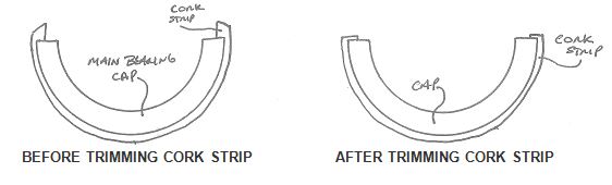
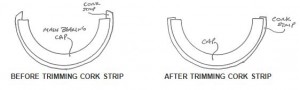
10. Install the cork strip in the groove/channel in the rear main cap and trim to length, as shown below. Trim it so that the ends of the cork slightly protrude from the end of the cap in such a way that the ends of the cork strip are parallel to the ends of the cap. You want the cork gasket to have some “crush” to it when the oil pan is bolted up. This is much easier to trim before installing the cap (otherwise, substantial trial and error is required). Although probably unneeded, you can place a small amount of silicone gasket sealant on the end of the cork strip immediately prior to final fitment of the rear main bearing cap against the block (before the silicon has a chance to set). Place the lower half of the rubber rear main seal in the rear main bearing cap and orient it according to the instructions;
11. After coating the lower main bearing halves with oil, replace the main bearing cap(s), including the rear cap, and torque them according to the shop manual specifications. Cleanliness is of paramount importance here.
12. Take apart and clean the oil pump. If the lower plate upon which the gears rest is worn, send the pump away for rebuilding. Unless it is broken, I would retain and re-use the same oil pressure regulator relief valve spring, since some rebuilders install a stiffer spring which would increase the oil pressure excessively and maybe cause more oil leaks! Before replacing the pump, fill it with Vaseline so that it is primed and will have pressure when you first start the engine. The Vaseline will then melt away.

13. Install the front cork seal, after trimming to length. This trimming is a careful, slow, iterative process of stuffing it in the groove, noting the excess length, removing the cork, trimming it slightly and test fitting it again and repeating as needed until done. Trim small amounts and sneak up on the final trimmed length. Again, you want a slight crush to the cork seal. Also, you want the ends of the cork seal to be parallel to the machined engine block surface. Here, as contrasted with the rear cork seal, you definitely want to seal the ends (tops) of the cork seal with a dab of silicone sealant just prior to final fitting (and just prior to installing the pan).

14. With the front and back cork seals now trimmed and in place, next test fit the side gaskets and trim them to closely abut the sides of the cork gaskets. Use as little silicone sealant as needed to seal the side gaskets to the cork gaskets. Use gasket sealant to hold the side gaskets in place against the underside of the block while you bolt the oil pan in place. Apply the gasket sealant only to the top surface of the gasket, since it will be easier to scrape the gasket off the machined engine block than off the ribbed surface of the oil pan next time this job has to be done.

15. Replace all parts mentioned in steps 3 through 7. When installing the oil pan, torque it to proper specs (10ft-lbs max). Do NOT over-torque or the pan will distort in the vicinity of the bolts and cause leaks.

16. When you start the motor, the first thing to do is make sure the oil pressure is normal. Then check for leaks. After 500 miles, re-torque all bolts, especially the oil pan bolts. Two of the oil pan bolts are above the starter, which will have to be removed temporarily to get at them.

If the engine has a lot of miles, then it would be prudent to replace the main bearings while doing the rear seal (and won’t cost much). If you were going to do more than just the main bearings and these seals, you would remove the engine, but this job can be done with the engine in the car. There is a trick to “spinning” the top half of the bearings out (using a flattened cotter pin inserted in the oil hole of the crank and turning the crank by hand). Taking off one bearing cap at a time, after installing the new bearings halves re-install and torque the bearing cap back on twice: the first time for a preliminary bearing clearance check with Plastigage; the second a permanent installation.

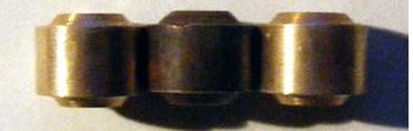
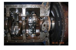
By the way, on a lift this job can be done in 4-6 hours, maybe a good bit less. It took me the better part of a weekend on a creeper since extra time was spent over-restoring some parts (powder coating the oil pan and some bolts, etc). NOTE: A high-quality torque wrench is the key to this job. You probably need two different torque wrenches. A low torque unit for the pan bolts (probably 1/4″ drive” and a stronger one for the main caps (probably 1/2″ drive). The specified torque on the pan bolts (and the valve covers) is so low that there is a substantial risk that you will over tighten them or under tighten them by a good bit if you use too large a torque wrench, with equally leaky results either way. Below is a picture of the rear cap reinstalled, with the cork gasket in place on its underside, just to the left of the flywheel in the right center.

oil leak 2 dec 08

brake dec 08

newsletter