Category Archives: Electrical

POWER WINDOW SWITCHES AGAIN

This is what I do to repair the Hydro Electric Window Switches when they start to act up. A lot of time, the nylon rod breaks from age and use. This makes the switches sloppy and prone to poor contact. This angers the driver when the windows sometimes fail to go up, or sometimes fail to go down. Removing the switch for the car is not terribly difficult – just be sure to mark the wires so you know where they go. If the wiring is original, be careful about handling it or you may have to use shrink wrap insulation if the cloth insulation comes off.

The pictures show the refurbishment of a 1953 Cadillac 4-gang switch, but the 1949 switch is the same as in all functional respects; only the chrome is a little different. Picture A shows a 4-gang switch disassembled. The orange wire or rod is weed wacker line, .095” in diameter. I have also used the tip off a broken fly rod instead, but finding broken fly rods is not easy!
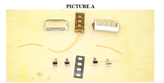
windows sw sep 10 1

PICTURE A

The most difficult part of disassembly is getting the spring clip/lock off (Picture A, top left) without damaging it or the housing. But if one is patient, one can get the two spring clips out of their holes and slide it off. Then everything just falls apart.

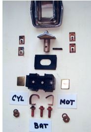
Picture B shows the toggles from two different perspectives, one with a nylon rod through it and three oriented to show the holes in the toggles for the nylon rod. It goes through all 4 toggles and holds them in place and ensures good contact on the spring surfaces. Both ends of the original nylon rod are tapered, but the weed wacker line will fit fine without the taper. If you have trouble threading it in, you could taper one end of the replacement line (rod) with a little sandpaper. These toggles are original to a 1949 Cadillac.
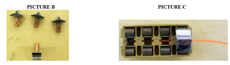
windows sw sep 10 2

PICTURE B PICTURE C

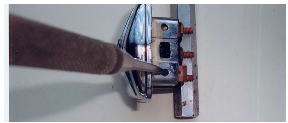
Picture C shows the base unit with one toggle installed and the orange nylon line partially installed. It takes a little patience to install the line, but really it is not that bad of a job. Red wine is a great shop assistant!

While you have the switch assembly apart, now is a good time to clean and polish things. Take time to clean up the housing. Also, take the springs out and polish them for better electrical contact. I generally clean them up just in case. A dab of dielectric grease might be used to maintain good electrical contact and avoid corrosion down the road.

When you get the toggles installed and the rod threaded the spring clip fits over the hole where the rod goes through. The clips hold the rod in place. Once done the switch toggles will be nice and tight and work a lot better.

newsletter

ANOTHER TAIL LIGHT AND LIGHT SWITCH TALE

During the 25 years I’ve owned my 6107, my tail lights have failed twice. Once was during a New England Region Driving Tour in the 1990s; the second was just a few weeks ago on a local street near my home. In both cases, I had turned on the headlights and a motorist admiring the car at a stop light pointed out the deficiency. Also, in both instances I assumed the problem was in the headlight switch and partially removed it to correct a loose wire.

Partially taking out the headlight switch, without detaching the many wires connected to it, is not difficult technically. However, it is a pain in the [choose your body part] because its location at the extreme upper left corner of the dashboard makes access difficult, particularly if you have large hands. The only reference to the switch in the ’49 shop manual is a picture of it on page 196, so I hope the following is an improvement.

1. Disconnect one or both cables from the battery and put the transmission in R (or in gear if a stick shift). Release the hand brake and unfasten the two bolts holding the bracket supporting the hand brake shaft from the bottom of the dash. Let the hand brake shaft and bracket hang down below its normal position.

2. The body of the headlight switch under the dash is box-shaped and roughly rectangular, about 3 inches (7.5 cm.) long from front to back, with several wires connected to it on both sides. Look at the illustration of the switch in the shop manual on page 196. You will see there is a “Knob Release Button” on the side of the switch facing the center of the car under the dash. Pull the exterior headlight switch knob fully out to its second (headlights on) position. With the hand brake mechanism now out of the way, lie on your back, slowly slide your hand up to the button on the side of the switch behind the dash and press the button. With your other hand you should now be able to fully extract (remove) the exterior headlight switch knob and its shaft from its place in the dash.

3. With the knob and shaft removed, the resulting empty hole in the switch bezel will accept a small Allen wrench, which you will then use to unscrew and remove the bezel.

4. The threaded dashboard end of the behind-the-dash part of the switch is now visible. Put your hand back behind the dash and push the rectangular part of the switch toward the front of the car until it is free of the dash. Then, with all the wires still attached, gently pull it down toward the bottom of the dash. This will take some twisting and pulling, but it can be done since the wires connected to the switch are relatively long. (Be careful that you don’t disturb the wires on the nearby fuel gauge.) Once it is pulled down and the switch body is visible, you can examine the headlight switch and its wires.

The first time I did this back in the ‘90s, the wire for the tail lights had become disconnected from the headlight switch for unknown reasons. Looking at the “Chassis Electrical” diagram on page 203 of the shop manual, you’ll see that the headlight switch is in the left center of the diagram and that the tail light wire is connected to the terminal numbered “3”. I re-connected the wire and solved the problem.

When this happened for the second time a few weeks ago I found the tail light wire still connected to Terminal 3, revealing to my great annoyance that I had partially removed the headlight switch for nothing. However, looking straight back under the dash to the upper left corner of the inner side of the firewall, I noticed something was not right with a large plug held in a clip attached to the firewall. This plug connects the under-dash part of the tail light wire harness with the back part of this same wire harness going to the rear of the car. (From this plug, the rear part of the harness runs up the side of the windshield, then between the headliner and the roof to the trunk and the tail lights.) The two halves of this plug had become disconnected from one another for some reason, so connecting them back together solved the problem.

5. Everything is put back in reverse order. An exception is the exterior headlight switch knob and shaft, which can merely be pushed back into its place in the bezel and switch without pressing the button on the under-dash part of the headlight switch.

newsletter

POWER WINDOW SWITCHES

After 60 years a common problem is that the window switch action is either erratic or not-at-all. This was the problem I found when restoring my ’49 Coupe de Ville. After searching for NOS parts, I decided that there must be a way to rebuild them.

Start by depressing the four spring retainers and pushing them out to where they can be pulled out, as in the photo below.
With the switch body out, carefully push the plastic pivot pin out. This pin can be easily broken, so be gentle with it. With the switch apart, the components can be cleaned of the dirt and corrosion. Re-assemble with the curved spring contacts as shown in the photo below. Re-assembly is simple and locked in place by inserting the four spring clips.

window 1 mar 10

window 2 mar 10

newsletter

IF YOUR AMMETER IS NEITHER POSITIVE NOR NEGATIVE, BUT IN BETWEEN THAT IS, DOESN’T WORK

…it’s not hard to fix. An ammeter will stop working for several reasons, a common one being that one or both of its two wires are broken, frequently within the wire harness sheath where it can’t be seen. To get it to work again, try running two new wires to it as follows:

1. Get about 10 feet or so of 16 gauge wire and, if you don’t already have this stuff, a box of assorted crimp-type connectors and a combination wire cutter, stripper and crimping tool;

2. Run one 16 gauge wire from the large terminal on the starter solenoid (to which is connected the positive battery cable) to the ammeter. Route this wire up to the firewall, then across the firewall, preferably behind the large wiring harness that runs horizontally low on the firewall, then up alongside the harness which leads to the large rubber grommet high on the driver’s side of the firewall. Push it through one of the holes in this large grommet to the area behind the dashboard and connect it to the positive terminal on the back of the ammeter;

3. Run a second 16 gauge wire from the BAT terminal on the voltage regulator, down along the wires from the regulator, then across the frame alongside the first wire, to the negative terminal of the ammeter.

The ammeter should now work. If it shows discharge when it should show charge and vice versa, reverse the 2 wires at the back of the ammeter. If the ammeter does not work at all with the new wires, it may be defective and in need of replacing. Make sure you buy a ’49 ammeter and not a similar-looking ’50. Also, it is important that the wires be no larger than 16 gauge as the ’49 ammeter is wired as part of a shunt system, which means only a small portion of the car’s electricity, 1 ampere or so, goes through the ammeter, unlike ’50 Cadillacs through whose ammeters all the electricity flows.

newsletter

A TAIL LIGHT TALE

by Art Gardner

My wife and daughter were following me home in my 6107 one night and reported that one of my tail lights was brighter than the other. At first I disbelieved them, but then thought they must be looking at one of the lights from not quite straight on. As you know, the tail light lenses have a focuser in the middle that creates a rearward beam, so I figured they each thought the one in front of them was brighter. However, checking myself I found they were correct: the left light was brighter. Switching the lenses from one side to the other didn’t help and I then noticed the bulb filament on the left lamp was lined up with the center of the focuser part of the lens, while the bulb filament on the right lamp was positioned noticeably below the focuser. As a result the focuser on the left lamp was getting a stronger dose of light than the right one.

Anyone run into this before? For the life of me, I couldn’t think of how you would adjust the position of the bulb relative to the lens…… Well, I think I have the answer. It appears the mounting boss into which the tail light socket is mounted is positioned below the “beam focuser” part of the tail light lens. To position the lamp at the level of the focuser, the factory made the mounting flanges on the sides of the sockets to be not perpendicular to the sockets, but canted at an angle. This points the bulb upward such that the filament is lined up vertically with the beam focuser. When I restored the housings, I must have installed the right side socket upside down, so that it points slightly down instead of slightly up. That caused the filament to be well below the level of the beam focuser, such that not as much light was traveling straight back through the beam focuser portion of the lens. I switched this around by undoing the two screws that secure the socket and twisting the socket 180 degrees. Now it lines up correctly. Here is a schematic drawing (exaggerated a little and not to scale) of what I am talking about. The moral of the story is that it appears that there is a correct orientation for installing the sockets (and an incorrect one).
BULB AND SOCKET MOUNTING FLANGE IS SECURED IN THE BOSS WITH 2 SCREWS

tail light dec 09

newsletter

NEW PROCEDURE FOR TESTING GAS GAUGE TANK UNITS

Chapter member Joe Foerster found a copy of, as he called it, “a snip” from the Nov.-Dec., 1948 Cadillac Serviceman’s bulletin, as follows:

A PROCEDURE FOR TESTING gasoline gauge tank units, which included lowering the gasoline tank in order to make the tank unit accessible, was announced on page seven of the February, 1948 issue of THE CADILLAC SERVICEMAN. In order to shorten the period of time required to replace this unit, the factory Engineering Department now recommends that the following procedure be used, which omits lowering of the gasoline tank. This new procedure takes less time than that allotted for lowering the tank in the old procedure. The new method is as follows:

1. Disconnect one of the battery cables.

2. Using a standard 4″ sheet metal saw, drill a 4″ diameter hole in the body floor pan directly over the gasoline tank float unit.

3. Disconnect the wiring from the tank unit.

4. Remove the screws which fasten the tank unit to the tank.

5. Lift out the tank unit. The float and arm will come away with it. Test the old tank unit against the dash unit. Failure may have been caused by poor ground.

6. Set the new tank unit with gasket, float and arm in exactly the same position on the tank. Install all screws and tighten securely.

7. Reconnect the wire to the binding post of the tank unit.

8. Fabricate a sheet metal cover for the 4″ hole in the body floor pan. Install this cover, seal with 3-M body sealer and secure it with at least six self-tapping screws.

9. Connect the battery cable.

Joe concludes, “Believe me. Once you’ve done this, you will wonder why the factory didn’t punch a hole there in the first place”.

gass sep 09

newsletter

COME BLOW YOUR HORN

by Art Gardner

Installing my 6107’s horns was one of the last tasks to complete after getting her running. I hooked up the wires to the horns, relay, etc and tried out them out. They blew for a second or two and then quit. So I had to take the horns off and give them a “tune up” by taking them apart, filing the points (using an ignition points file), cleaning them up internally, adjusting the points to give a consistent tone, painting, etc.
The task of adjusting the points is a bit irksome, as it will annoy the neighbors! Basically, you turn the adjustment nut while energizing the horn with a couple of wires until a good sound comes out of the horn. After reinstalling the horns, all that was left was to install the horn button and horn ring. That job took a little bit of patience in order to make the system work reliably, as described next.

To get the horn ring and button working right, I first had to adjust the longitudinal position of the steering shaft relative to the steering column. This was because I had changed this positioning inadvertently as part of the installation of a rack and pinion steering unit. This is not necessary on cars with stock steering.

Next came the task of trying to find the right replacement for the fiber washer that originally was fitted under the little contact at the top of the steering shaft. As you can see in the schematic below of a generic Cadillac steering wheel, the horn button (7.3785) is held away from the steering shaft by a conical spring (7.3796) which rests at its small end against the nub of the contact (7.3820).
The contact has a flange and a shank (not seen in this parts diagram). I thought that the horns were energized by the flange of the contact touching the top of the steering shaft. But that is not the usual manner of blowing the horn. Instead, the flange is held slightly away from the top of the steering shaft by the washer, even against the force of the horn button spring. When the horn ring is pushed, it causes the contact to tilt slightly in the same direction as the horn ring. The lower tip of the contact apparently then touches the inner wall of the steering shaft, completing the circuit. See my sketch (not to scale and a little rough, but you will get the idea). The trick then is to come up with a decent replacement for the washer that will be thick enough to keep the flange from contacting the top surface of the shaft and yet will allow the horn to blow when the horn ring is tilted. Jay Friedman told me that some folks take a small rubber band and wrap it around and around the shank to make a replacement. I tried that, with poor results. The car had an O-ring on there as some previous owner’s attempt at a repair, but it wasn’t doing the job.

june 09 horn1

june 09 horn2

What I came up with is a bit of rubber grommet as shown in the drawing above. I cut the grommet with a scissors to make a suitable collar to wrap around the upper part of the shank of the contact. To slip it over the shank without removing the horn wire from the shaft, I simply sliced it lengthwise (split it) with the scissors. Since it is captured in the bore, the split in the rubber is of no consequence. I found that a grommet with a 3/16″ ID worked well. Alternatively, a bit of rubber hose with a similar diameter would work as well. It takes some careful trial and error to get the length of the rubber /grommet just right, but I managed in 4 attempts. The set up works well and my car has working horns for the 1st time in 2 decades

newsletter

COME BLOW YOUR HORN

by Art Gardner

Installing my 6107’s horns was one of the last tasks to complete after getting her running. I hooked up the wires to the horns, relay, etc and tried out them out. They blew for a second or two and then quit. So I had to take the horns off and give them a “tune up” by taking them apart, filing the points (using an ignition points file), cleaning them up internally, adjusting the points to give a consistent tone, painting, etc.
The task of adjusting the points is a bit irksome, as it will annoy the neighbors! Basically, you turn the adjustment nut while energizing the horn with a couple of wires until a good sound comes out of the horn. After reinstalling the horns, all that was left was to install the horn button and horn ring. That job took a little bit of patience in order to make the system work reliably, as described next.

To get the horn ring and button working right, I first had to adjust the longitudinal position of the steering shaft relative to the steering column. This was because I had changed this positioning inadvertently as part of the installation of a rack and pinion steering unit. This is not necessary on cars with stock steering.

Next came the task of trying to find the right replacement for the fiber washer that originally was fitted under the little contact at the top of the steering shaft. As you can see in the schematic below of a generic Cadillac steering wheel, the horn button (7.3785) is held away from the steering shaft by a conical spring (7.3796) which rests at its small end against the nub of the contact (7.3820).
The contact has a flange and a shank (not seen in this parts diagram). I thought that the horns were energized by the flange of the contact touching the top of the steering shaft. But that is not the usual manner of blowing the horn. Instead, the flange is held slightly away from the top of the steering shaft by the washer, even against the force of the horn button spring. When the horn ring is pushed, it causes the contact to tilt slightly in the same direction as the horn ring. The lower tip of the contact apparently then touches the inner wall of the steering shaft, completing the circuit. See my sketch (not to scale and a little rough, but you will get the idea). The trick then is to come up with a decent replacement for the washer that will be thick enough to keep the flange from contacting the top surface of the shaft and yet will allow the horn to blow when the horn ring is tilted. Jay Friedman told me that some folks take a small rubber band and wrap it around and around the shank to make a replacement. I tried that, with poor results. The car had an O-ring on there as some previous owner’s attempt at a repair, but it wasn’t doing the job.

What I came up with is a bit of rubber grommet as shown in the drawing above. I cut the grommet with a scissors to make a suitable collar to wrap around the upper part of the shank of the contact. To slip it over the shank without removing the horn wire from the shaft, I simply sliced it lengthwise (split it) with the scissors. Since it is captured in the bore, the split in the rubber is of no consequence. I found that a grommet with a 3/16″ ID worked well. Alternatively, a bit of rubber hose with a similar diameter would work as well. It takes some careful trial and error to get the length of the rubber /grommet just right, but I managed in 4 attempts. The set up works well and my car has working horns for the 1st time in 2 decades

newsletterjune 09 horn1

june 09 horn2

SEMI TECH TIP

When I installed a new directional signal flasher to see if I could breathe new life into my squirrelly directionals, I discovered that the prongs had to be just so in order for the flasher to squeeze into the socket. Otherwise mashing the two together might do some damage. I just closely eyeballed the prongs on the old one and the new one and bent as needed. They were just different enough to prevent an easy install.

newsletter